


 Our PCBs for Education program enables us to help future engineers by actively partnering with professors and students in support of their classroom engineering projects and team competitions by providing printed circuit board manufacturing services. This month we’d like to highlight one such group, the University of Florida Solar Racing Team which aims to spread awareness for solar energy by designing and building a solar-powered race car to compete in the American Solar Challenge (ASC). From the Solar Gators:
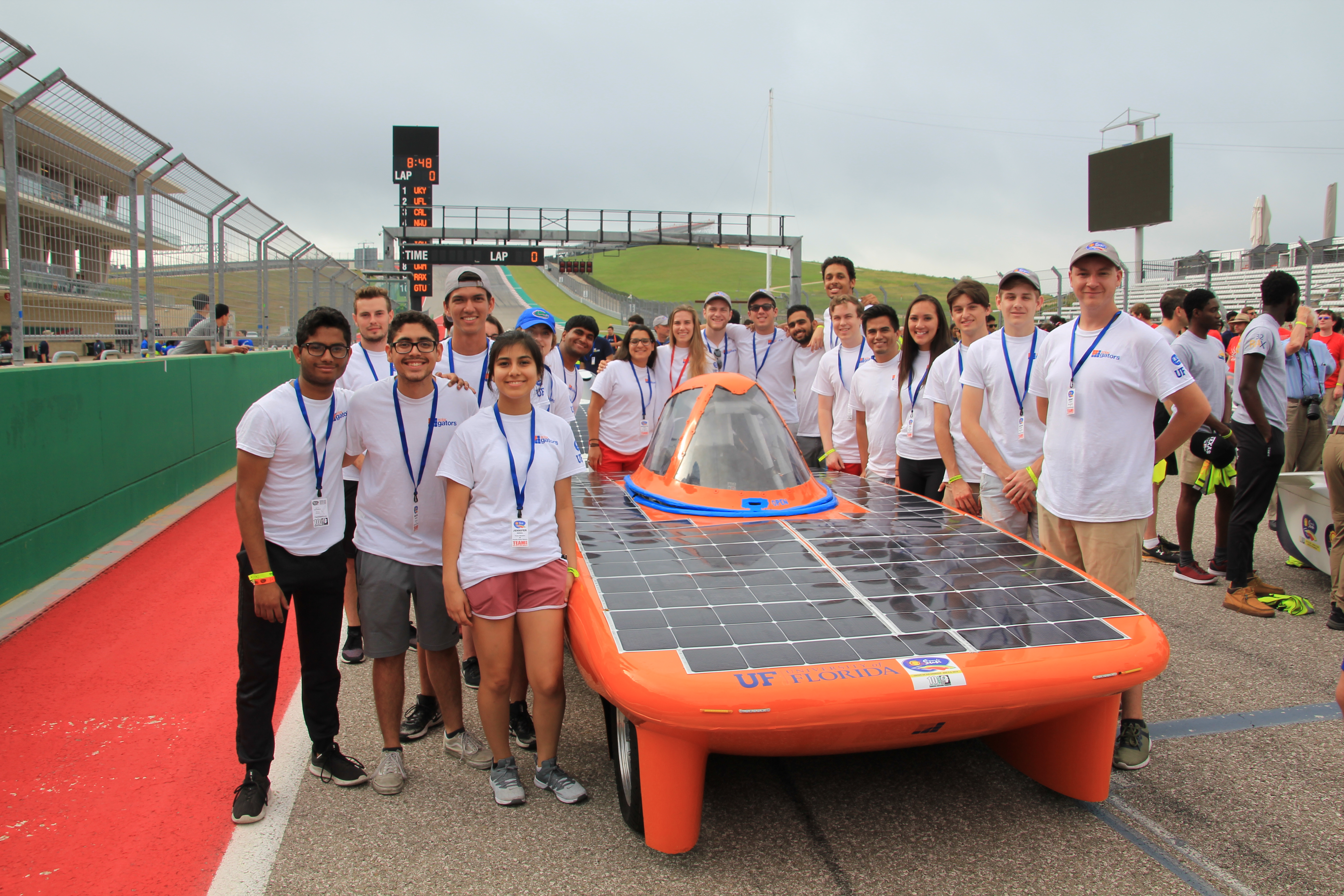
We would like to thank you for your support of our Electrical Systems during our 2018-2019 design cycle. On July 6th, 2019, our team competed in the Formula Sun Grand Prix at the Circuit of the Americas in Austin, TX. Our remodeled car, Cielo, was incredibly successful and completed 206 miles – over ten times as many miles as the year prior.
Bay Area Circuits’ PCBs were the foundation of all electrical systems of the car and performed excellently across the board. Many systems were completed in time for racing, while some are still in development for future events. We would like to provide short descriptions of how we used your PCBs along with future work that we will be undertaking during the 2019-2020 design cycle.
Again, we are incredibly grateful for Bay Area Circuits’ sponsorship of our team and are confident we will continue to see outstanding results when using your PCBs.
POWER SYSTEMS
Description
This Bay Area Circuits PCB holds four DC-DC converters that regulate power from our 96V battery pack into various DC supplies for all systems of the solar car. A 12V, 5V, and two 3.3V rails are generated by this board. Also on this PCB are power muxing components that, in the event of pack isolation in a battery fault, supply power to critical systems using a supplemental battery. Additionally, this board has an array of fuses to protect systems of the car from high current surges.
Future Work
We used a backup system of conventional diodes for power muxing due to time constraints, but we would like to test with the ideal diodes that we had originally intended for this purpose. We also had a few EMI filters on the board that were not used because our power supply from the batteries was steady enough. Removing these in future boards will decrease area to fit increasingly smaller enclosures designed for the car’s efficiency. Finally, some of the traces on the board were cut, some connections had to be made, and some components did not fit their footprints. These minor errors will be fixed in the newest version of the board.
AUXILIARY SYSTEMS
Description
Our Auxiliary systems were built on a Bay Area Circuits PCB. This board controls all non-critical and human-interface features of the car, like brake lights, turn signals, headlights, and regenerative braking. The board mounts inside the car’s dashboard, and an onboard-ARM microcontroller reads switches to operate the various peripherals. Due to late software issues, this board was not operational during competition, but recent developments with the board have shown positive progress.
Future Work
For the following year, we plan on increasing the Auxiliary System’s functionality by reducing the amount of wires going to the board with the implementation of the CAN bus. Unlike the previous revisions, the shape will be irregular and non-rectangular to fit the custom steering wheel that will encapsulate the PCB. This new layout will have smaller switches and buttons directly soldered to the board to minimize hardware, such as a bulky switch box and numerous wires, which would in turn reduce the total car weight and improve space efficiency. We plan on taking advantage of the two layers so that we can make the boards as compact as possible.
BATTERY MANAGEMENT SYSTEM
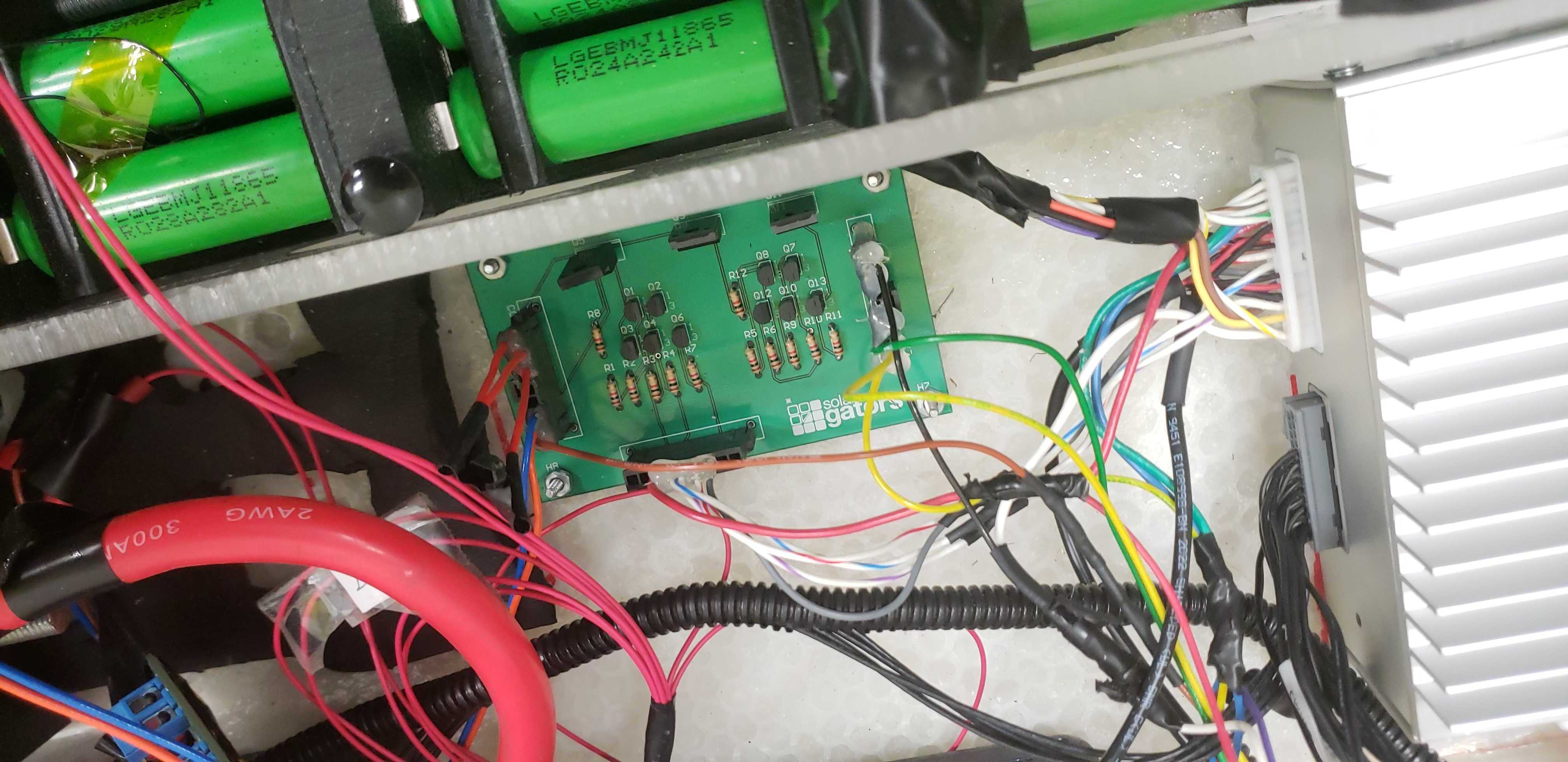
Description
Our battery management system uses a Bay Area Circuits PCB for battery fault logic and contactor control. A separate system monitors pack voltage, current, and temperature and generates signals representing the state of the battery. This logic on the PCB combines these signals and operates power transistors to control high-voltage automotive contactors.
Future Work
In the 2019-2020 design cycle, we will be revamping the battery fault logic hardware, to increase efficiency of the car. We will transition to CMOS transistor logic to improve overall efficiency. By early 2020 we will be creating our first prototype for a custom BMS. This will entail having daughterboards that will manage each battery modules temperature, voltage, module resistance. A motherboard will control each daughterboard and will generate signals that will output to the battery fault logic board.
MAXIMUM POWER POINT TRACKERS
Description
The Maximum Power Tracker is the Dynamic DC-DC converter between the solar arrays on our car and the battery pack. The purpose of this board is to optimize power harvesting by combining power electronics and implementing a power point tracking algorithm using a microcontroller. The design has 2 interleaved boost converters, designed to support higher overall power and reduced ripple. Some challenges regarding designing the PCB were unique to designing switching power supplies, such as keeping areas with high dI/dt’s small.
Future Work
Throughout the testing of the MPPTs, our engineers realized some crucial design points were missed. For example, to achieve current balancing between the two interleaved boost converters, current mode control needed to be implemented. Without current mode control, one converter would eventually overload, frying the converter. The engineer also decided to go from direct duty cycle control, the control this board uses, to analog control, using an IC and external passives to implement proper loop stability. This frees up the microcontroller to focus solely on the tracking algorithm as opposed to attempting to both track and keep the control loop of the power supply stable. Since this is a mixed-signal circuit, the team anticipates the need for developmental iterations in order to ensure fidelity and speed of control signals within the circuit.
TELEMETRY SYSTEMS
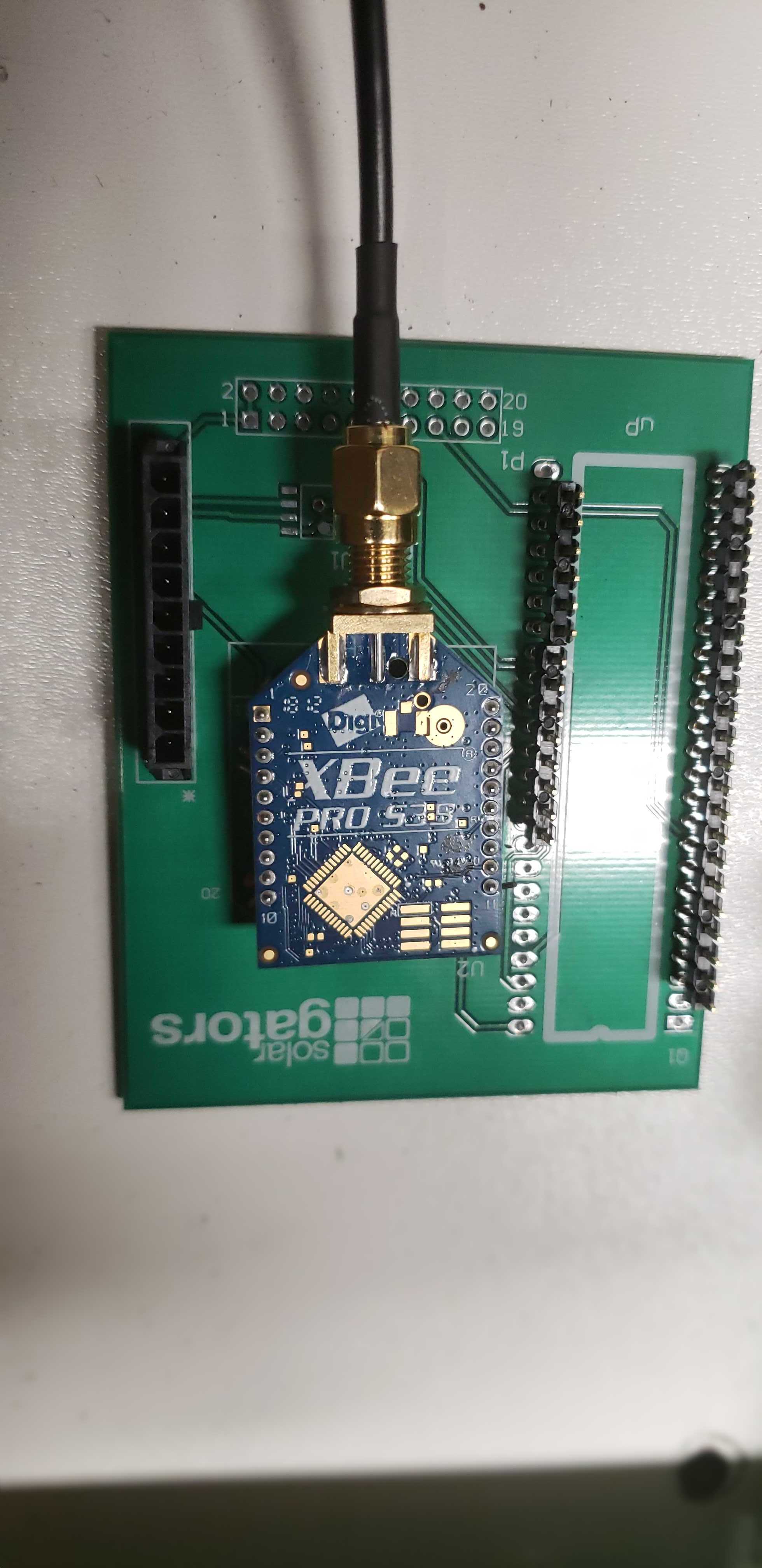
Description
Our telemetry systems is an ongoing project to enable wireless data communication between our car and team members in the pit area. This PCB has an RF transceiver operated by an ARM microcontroller the receives messages from our car’s Controlled Area Network bus and transmits them to the pit. Unfortunately, component quality and availability hindered this project’s development; specifically, the antenna took months to arrive. This year, our team is renewing focus on this system, and placing greater importance on it, with a larger team size and more experienced members.
Future Work
During competition we realized we would’ve performed much better if we had better models to decisions off of – hence the call for more focus on telemetry. We will be continuing the design with a microcontroller and a software-defined radio, further maturing the design. We will design the board to translate digital data from the CAN Bus to an analog radio signal, and a board to take the analog signal and convert it back to the digital realm. With more focus on upgrading this subsystem we are excited to see how our performance will improve once again.


Thanks to the Solar Gators for taking the time to share their progress!